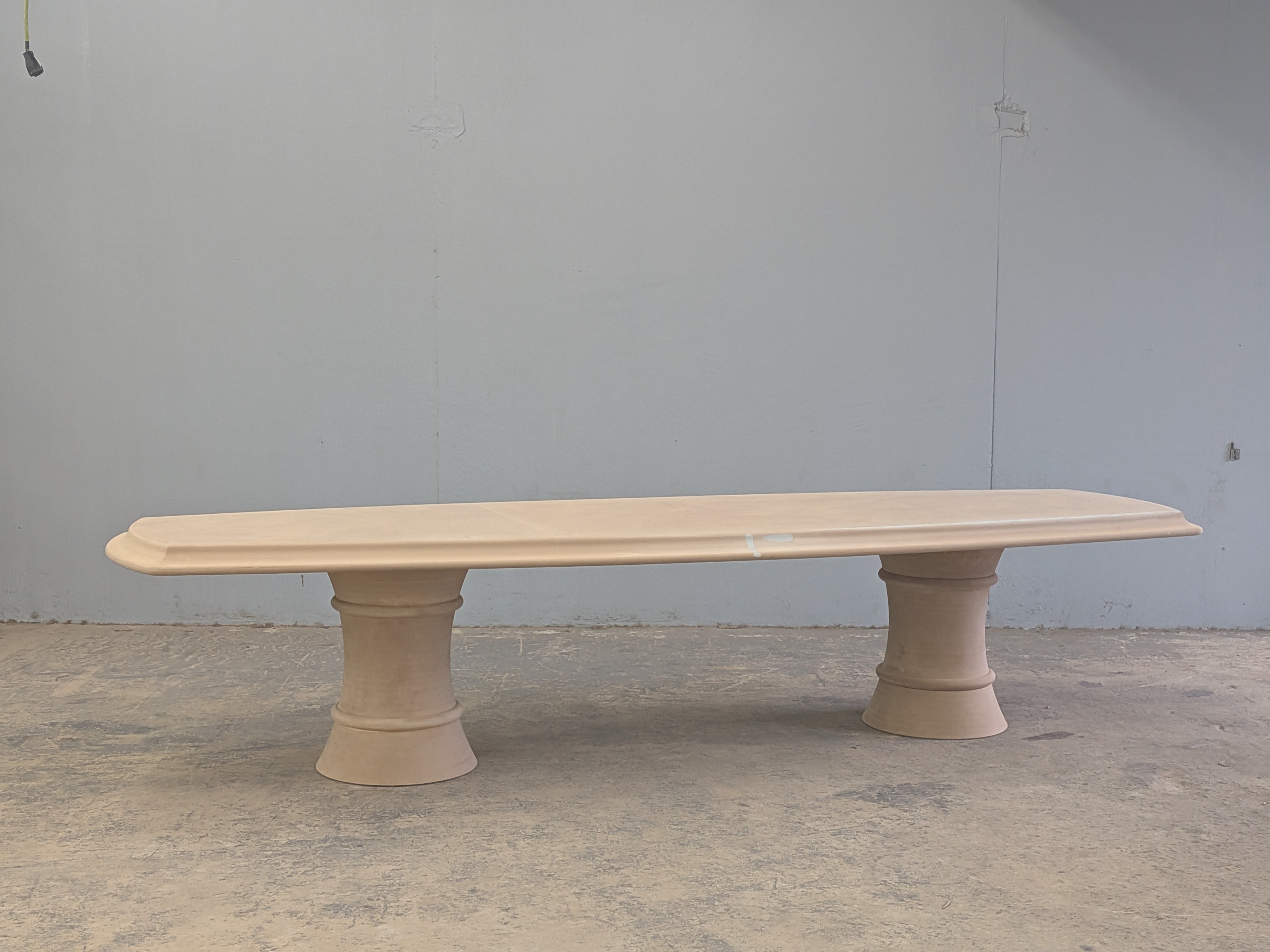
ALD Dining Table
Custom-profile dining table engineered for plaster finish using CNC-sliced MDF assembly
"Custom profile had to accept plaster without cracking — ruled out solid wood. MDF was the stable choice, but our trusted lathe team couldn't get a reliable glue-up blank at the size we needed, so the whole workflow had to shift to CNC."
The table came through a designer with a private client. The brief was specific: a custom profile that could be plastered for texture. Not stained, not lacquered — plastered. That one detail changed everything downstream.
The Material Problem
Plaster doesn’t flex. Wood does. Put a solid wood substrate under a plaster finish and you’re waiting for the seasons to change and the surface to crack. The solution was obvious once you named the problem — MDF. Dimensionally stable, no grain movement, takes plaster cleanly.
But MDF created its own problem. Our usual team for large-scale turning work couldn’t get a reliable glue-up blank at the size we needed. MDF doesn’t behave like hardwood in a laminated turning blank — the mass, the glue behavior, the way it loads a lathe — it wasn’t going to work with their setup. So the lathe path closed, and we had to figure out a different way to get the same profile.
The CNC Solution
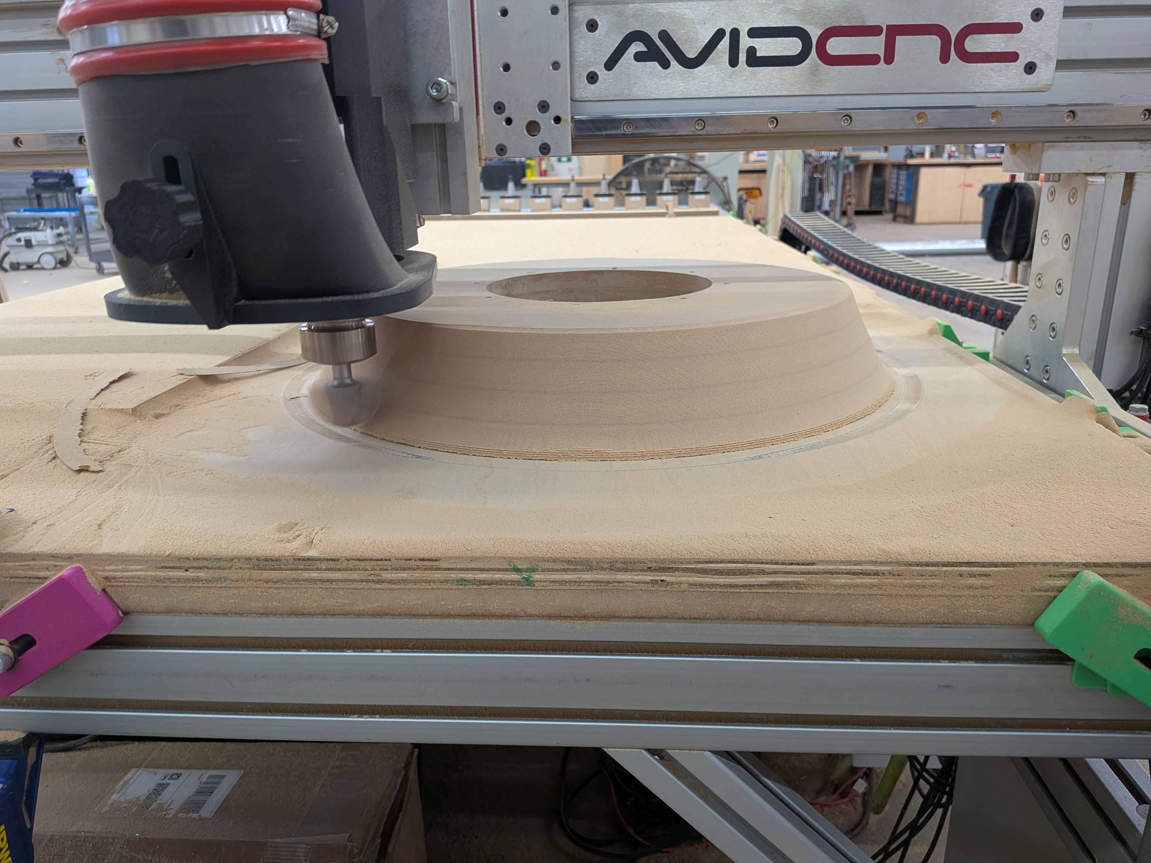
We went back to the machine. The question became: what’s the largest slice we can cut reliably, and can we get the full profile by stacking and gluing those slices?
The answer was 5.5 inches per pass using a 2-inch roundover bit. That bit selection wasn’t arbitrary — it also kept the spindle out of the way on the steeper climbs in the profile geometry. Once we had that constraint defined, the whole workflow snapped into place.
The Assembly Workflow
The sequencing mattered as much as the cutting. For the table top — which had to be four layers thick — the seams couldn’t stack. A seam that runs through all four layers is a crack waiting to happen. So we mapped every seam offset before cutting anything, confirmed the layout in the model, then cut.
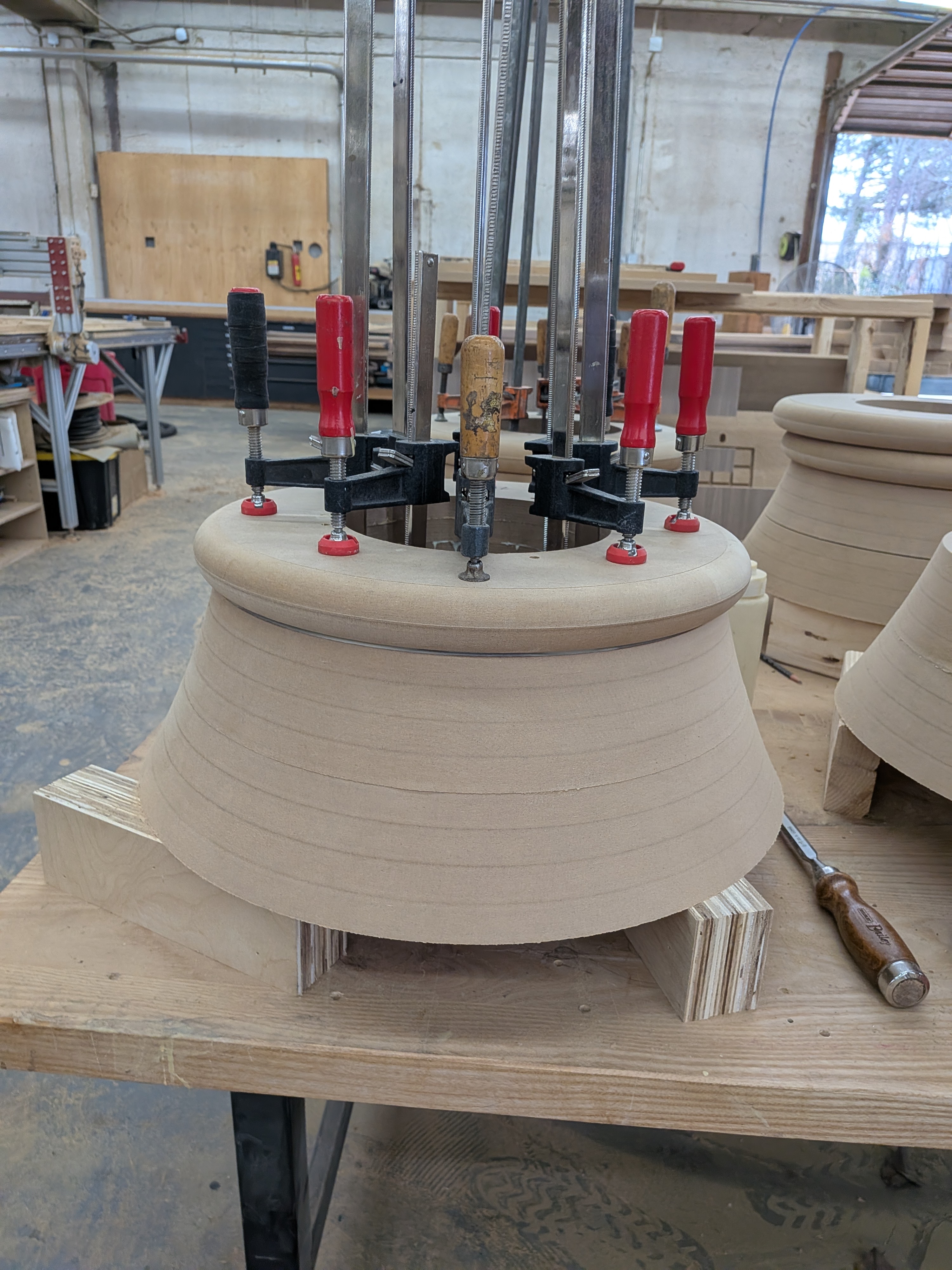
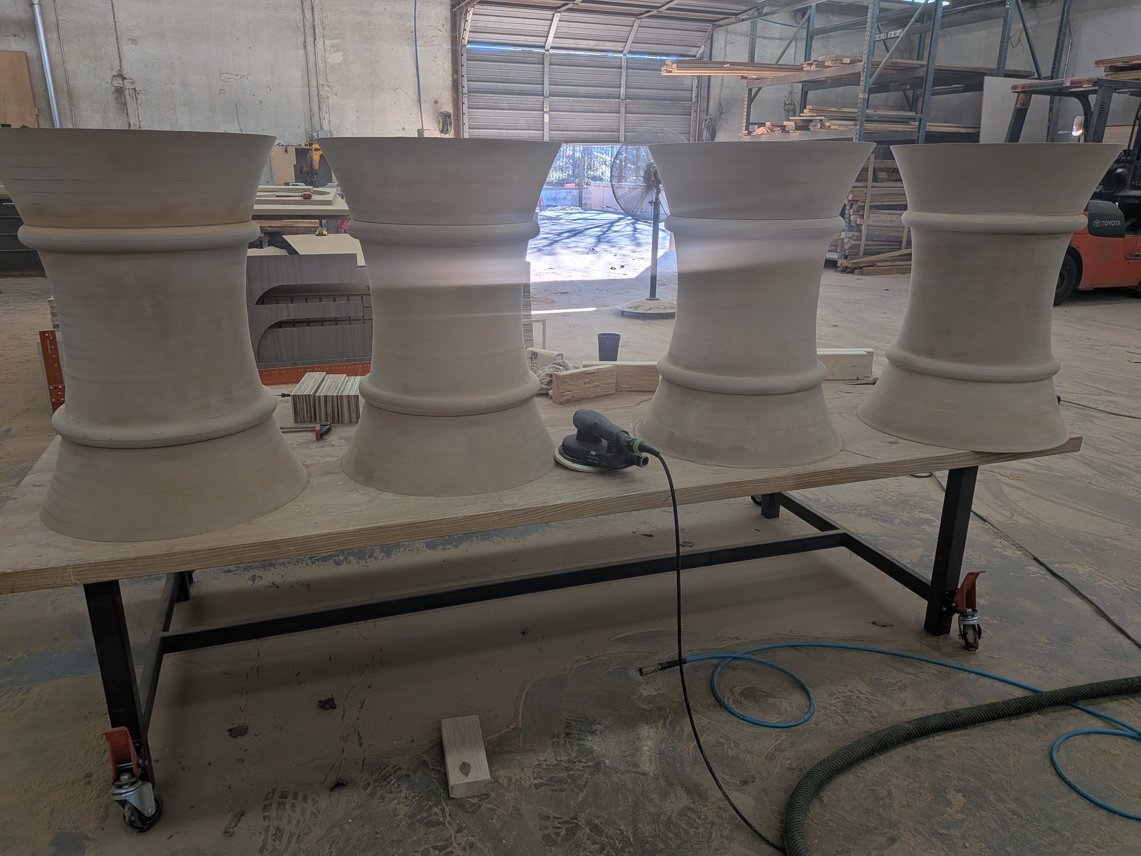
The legs followed the same logic. Cut all the component slices. Glue them into smaller sub-stacks. Cut those sub-stacks down into the carved profile sections. Glue those up into the final leg assemblies. Finish sand. It was a lot of passes and a lot of glue-up time, but every step was planned before the first cut.
The Jig Problem
The carved pieces came out as donut profiles — rings with a shaped cross-section. Those shapes don’t clamp conventionally. Nothing in the standard fixturing kit holds a ring flat while the machine carves the face. So we built hold-down jigs specific to this profile, sized to the exact dimensions we were running. Getting that right was a requirement, not a refinement — without it, the pieces move and the carving is ruined.
I led the carving programming and all CNC setup for this project. The jig design was part of that scope.
The Result
Client and designer were both happy. The profiles came out consistent across all pieces, the seams disappeared into the assembly, and the table was ready for the plaster finish it was designed for. The kind of project where the planning work is invisible in the final piece — which is exactly how it should be.
- Solved a materials conflict most shops would have missed — recognized early that solid wood movement would crack the plaster finish and specified MDF before any material was ordered
- Developed a CNC slicing workflow that substituted for lathe turning when the lathe path closed — 5.5-inch passes with a 2-inch roundover bit across all profile components
- Offset seam layout across four layers eliminated weak points in the table top assembly without adding material cost
- Fabricated custom hold-down jigs for donut-profile pieces — no off-the-shelf solution existed for this shape
- Led all carving programming and CNC setup for the project